
SDI-12 sniffer based on Raspberry Pi
This post is about building SDI-12 sniffer which listens to serial communication on SDI-12 bus in long-therm (lets say days or weeks) and saves each command and response with its timestamp into text files. These files are stored localy in SDI-12 sniffer and also they are sent to e-mail authomaticaly so they can be checked regularly and remotely. This post is specificaly about SDI-12 communication, but with modifications it could be used for any serial communication debugging.
Problem to be solved
I found myself looking for cause of weird bug in datalogger with some SDI-12 sensors connected to it. It was one of those irregular random bugs. Most of the time the communication was working normaly, but from time to time (days, weeks…) the communication stopped working temporarily causing gaps in measured data. I didn’t know if the datalogger is causing this issue or if it is one of cheap sensors I were testing which disrupts communication somehow.
I’ve already had some nice SDI-12 to USB coverter. It is great for working with SDI-12 sensors in real-time. You just open terminal and it is possible to act as master to your SDI-12 sensor or listen to ongoing serial communication on SDI-12 bus. But I needed to let terminal / serial monitor run for weeks, catching all the communication untill some missing data will appear again.
What is SDI-12?
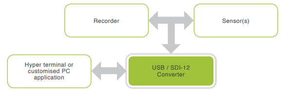
SDI-12 is both serial communication protocol and HW interface description. SDI-12 stands for Serial Digital Interface at 1200 Baud. It is simple protocol using fixed baudrate and ASCII characters for commands and responses. It is commonly used in collecting environmenal data where one datalogger is typically connected to multiple SDI-12 sensors which are all on the same bus and each sensor has unique address. These dataloggers are often on remote location with no access to grid so they are battery powered and low power consumption is a must. Volume of data sent by sensor during communication is very low (each sensor returns typicaly just few parameters). More information and complete specification can be found on https://sdi-12.org/.
Listening to SDI-12 communication
SDI-12 to USB converter I was using is TekBox TBS03. There are multiple versions of this converter which all have the same dimensions and look, but differs in features and price. The version I was using was the “middle one” which is called TBS03/OTBS03-1 and can be used in so called “SDI-12 monitor mode” which means that converter acts as sniffer which listens to ongoing communication on SDI-12 bus without disrupring it. More information about this converter and how to use it can be found on TekBox website.
You can use any application which acts as serial monitor (PuTTY, HyperTerminal, Arduino IDE Serial Monitor etc.) to connect to the SDI-12 converter. Use the following settings: baudrate 19200, 8 data bits, no parity, 1 stop bit, no handshake.
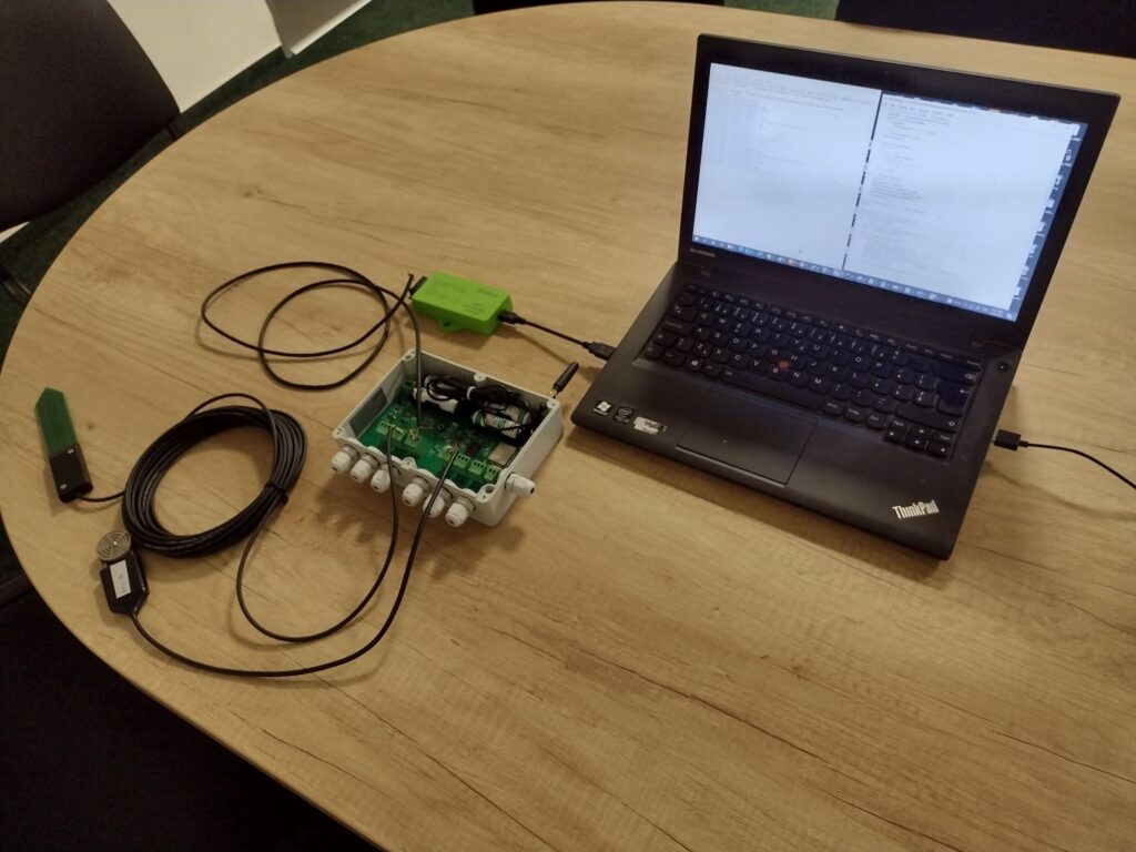
I have connected SDI-12 converter to SDI-12 bus using just two wires: ground and data, although SDI-12 devices usually use three wires (ground, data and power). That is because datalogger (recorder) is acting as power supply for sensors in this case and TekBox converter is powered from USB. Whole setup can be seen on picture bellow. There is datalogger with two SDI-12 sensors connected to it and then SDI-12 converter (small green box) which acts as interface between USB port on Windows machine and SDI-12 bus.
Serial monitor program using Python
I made my own serial monitor program using Python which reads serial output from TekBox SDI-12 converter. Output from this program is shown bellow.
In this example you can see that datalogger was reading data from two SDI-12 sensors. First sensor has address 6 and and returns 5 measured values successfully. Second sensor has address 3 and does not respond at all so datalogger tries to initialize measurement multiple times with 3M! command.
Note that each command and response is marked with timestamp. Precise timestamp is important when debugging SDI-12 communication as some bugs may be caused by wrong timing.
Python code can be seen bellow. This program also writes each line with its line number and timestamp into file called “sdi12_monitor.txt”.
Sending e-mails using Python
I created also the second Python program which reads “sdi12_monitor.txt” text file and sends its content to my mail. This program also changes name of text file “sdi12_monitor.txt” containing data. It adds prefix with current date in mmddYY format. For example file which contains data which were sent to e-mail on 15th June 2022 would have name “06152022_sdi12_monitor.txt”. You can see example code bellow.
I was using my gmail account. SMTP server domain name is smtp.gmail.com and port number 587 in this case. If you are using different provider (Yahoo, Outlook etc.) you have to change SMTP server and port number accordingly. Please note that in example code, you have to change e-mail adresses and Google App Password to make it work with your Google account. Google App Password is not the same password which you use normaly to log into your e-mail or Google account. Google generally uses so called ”2-Step verification” for higher security. This prevents our Python program from logging in using our standard Google password. For logging in from our Python program, it is best to generate and use Google App Password. Google says:
When you use 2-Step Verification, some less secure apps or devices may be blocked from accessing your Google Account. App Passwords are a way to let the blocked app or device access your Google Account.
More information about how to create and use Google App Password can be found here.
Running from Raspberry Pi
Hardware
Once both Python scripts were finished and tested on Windows, next step was to make it all work on Raspberry Pi. Raspberry Pi is perfect for SDI-12 sniffer build as it is portable, cheap, can run nonstop for long time without consuming too much energy or producing noise and I just love it 🙂
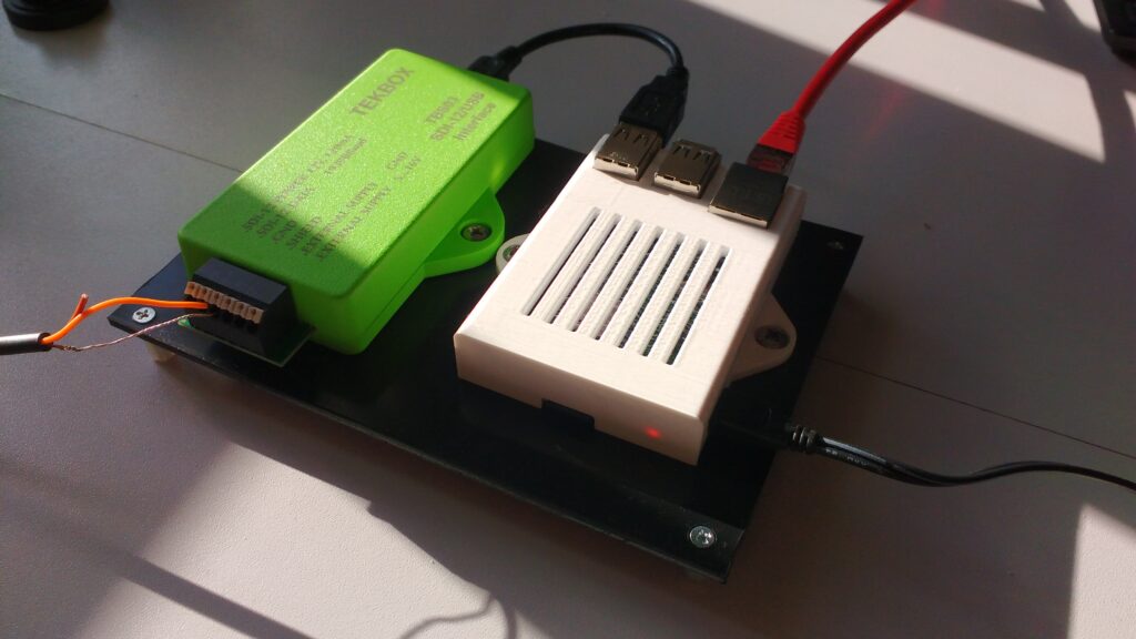
TekBox converter was connected into USB port of Raspberry Pi 3 Model B+. I 3D printed Raspberry Pi case. Model is based on popular Sleeve Case for Raspberry Pi published in Thingiverse. I have modified it sligtly adding two mounts which matches TekBox converter case design. My version of Raspberry Pi case can be found here. Unfortunately I didn’t have green filament in TekBox converter color around so I printed it in white PETG 🙂
Both TekBox converter and Raspberry Pi were then fitted to piece of black plastic with distance posts mounted into its corners. The Raspberry was connected into the local network using Ethernet cable. Complete SDI-12 sniffer assembly can be seen on picture bellow.
OS installation and basic setup
I used SD card for Raspberry Pi with preinstalled Raspberry Pi OS and NOOBS. I inserted SD card, connected power supply, keyboard and connected Pi to monitor using HDMI port. To proceed with instalation internet connection is needed. The process of instalation is really easy using NOOBS. I have chosen 32 bit Raspberry OS lite version (without desktop environment). Once the installation is complete, it is convenient to enable SSH connection so we can later disconnect Raspberry Pi from monitor and keyboard and continue configuring it remotely. To do that start raspi-config configuration tool by typing
and then choose “Interface options” and enable SSH server.
Setting static IP address
Pi’s IP address is dynamic now. It is nice to set static IP address to Raspberry so we don’t have to bother with exploring what is the current IP address when we want to connect to it.
To set it we need to find out what gateway IP address and DNS server IP address is.
To get gateway IP address use following command:
Response can look like this:
I am going to use wired connection so looking on first IP address on row with “eth0” string I can see that my gateway IP adress is 192.168.0.1.
Then we need DNS server IP address. We can find that by checking contents of “resolv.conf” file using command:
Nano text editor opens. And my file looks like this:
To exit nano text editor, just press CTRL+X. Now we can launch network manager by typing nmtui. Select: Edit a connection -> Wired connection. Navigate to IPv4 CONFIGURATION and change <Automatic> into <Manual>. Then navigate to <Show> (on the same line) and press enter. Then enter the static IP adress of your device, Gateway IP address and DNS server IP adress. When all addresses are set navigate down to OK and confirm. Then select BACK and lastly select QUIT.
We also have to run following command so the changes take effect.
Or we could reboot Raspberry Pi using “sudo reboot” command
There is also good video tutorial about setting static IP address here on YouTube:
Older systems use dhcpcd.conf file to set static IP address.
To use static IP 192.168.0.15 with wired connection and previously mentioned router settings I need to add following lines to the file.
Now that the IP address is static I will be always able to access it on IP address 192.168.0.15 from local network using SSH connection. I am using PuTTY for that.
Running Python scripts
To transfer file with Python program from Windows machine into Raspberry I used PSCP which stands for Putty Secure CoPy. This program runs from Windows Command Prompt. To use it, open Windows Command Prompt first and then navigate into directory, where your Python programs are saved. Then you can use following command:
In this particular example we are uploading file called “serial_monitor.py” which is our Python serial monitor program to our Raspberry Pi with previously set static IP address 192.168.0.15 and as user with name “pi”. Bear in mind that it is local IP adress so both Windows machine and Raspberry have to be in the same local network. I uploaded both python files into the same python_proj directory.
Then you can connect to Raspberry Pi using SSH and navigate into the folder where the python file was uploaded (“/home/pi/python_proj” in my case). To be able to run the program we have to install python serial library.
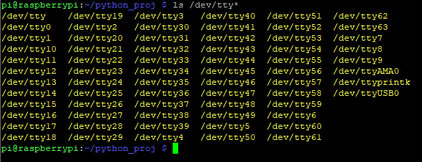
Next step we have to change COM port. Type following command:
In response bellow note the port number listed for /dev/ttyUSB* or /dev/ttyACM* . The port number is represented with * here. My COM port will be /dev/ttyUSB0.
Open serial_monitor.py file using nano text editor and change PORT constant. Now it should be possible to run the python script.
Next step would be to transfer to Raspberry Pi also the second Python script (for sending e-mails) using PSCP. This file should be in the same directory as serial_monitor.py script. Because we are now sending e-mails from different machine we have to create new Google App Password and update our Python script accordingly. We can then test-run our script for sending e-mails.
Setting up cron
To run Python program for sending e-mails and renaming text file with data periodicaly I used cron. Cron is standard part of Linux operating systems and its purpose it to run some programs periodicaly on some predefined schedule. To add new tasks open your cron table using “crontab -e” command. If you want to just view your crontab file, you can use “crontab -l”. Each cron task is on separate line and starts with multiple numbers. These numbers stands for minutes, hours, day in month, month, and day in week where 0 is for Sunday. Using * character means arbitrary value. I wanted to run my program every day at 00:30 in the morning so I added this line:
Last step is to start the serial monitor program. We can let it run in background using following commands:
Analazing captured data
After few days of operation there will be multiple text files with captured communication stored in Raspberry Pi “python_proj” project directory (one file per day). We should also receive one e-mail per day (with the same contents).
There are more possibilities how we can access captured data:
- we can check data on e-mail
- we can connect to Raspberry Pi using SSH and check files contents
- we can transfer files to our Windows machine using PSCP and analyze it there
First two methods are pretty straightforward. I will now explain how to download files uning PSCP. First open Windows command line. Then navigate into destination folder where you want to download data to. Once you are in folder use pscp command as in following example:
In this particular example we are downloading one file called “sdi_monitor06212022.txt” which is stored in folder “/home/pi/python_proj” on our Raspberry Pi with IP address 192.168.0.15. This particular file was created on 21st June 2022. Your working directory will contain many files if you run long-therm test as I did so it is not very convenient to download files one by one. Luckily you can use “wildcards” with PSCP and download all files using one command as shown in this example:
Conclusion
This SDI-12 sniffer helped me to understand cause of the issue described at the beginning. The datalogger became sometimes “deaf” and also did not behave according to SDI-12 specification when it happened. I hope you found this post useful and easy to follow. Please let me know if you have any questions regarding this topic or also if you have ideas how it could be improved. I think it would be nice to get rid of expensive SDI-12 to USB converter and replace it with some SDI-12 Raspberry Pi shield instead.
If you want to be notified about new posts and updates consider subscribing to my mailing list.